

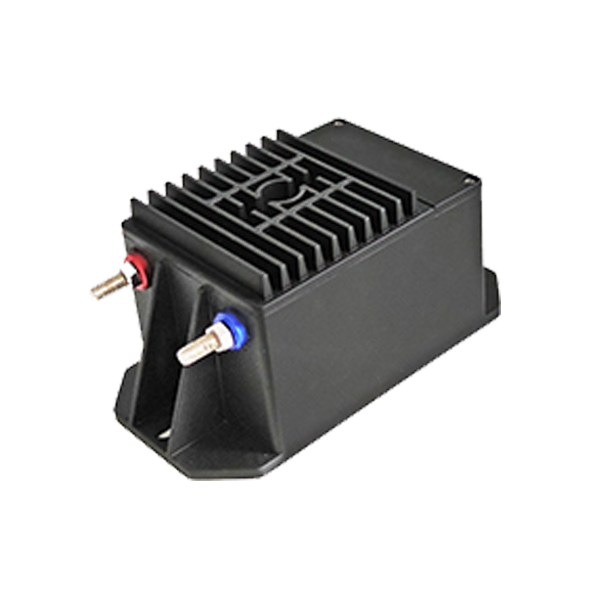
A receiver can change the voltage signal it is intended to observe. For a DC voltage transducer, the stated conversion ratio therefore belongs beside the electrical load connected to its output. A proportional signal becomes a usable measurement only when that receiving circuit is included in the relationship.
The primary side’s voltage range and insulation constrain the installation; the secondary circuit’s loading determines how its proportional signal is presented to the acquisition stage under actual connection conditions.
Form a Proportional Signal Across Separate Circuits
The sensing process begins with a current-limiting resistance associated with the voltage input. Current resulting from the applied voltage produces a magnetic field, which magnetic modulation detects. The resistance relationship allows the voltage to be determined through Ohm’s law. The measurement follows a sequence from voltage to current, magnetic detection and a proportional secondary signal.
The input resistance participates in sensing the measured primary voltage. A resistance in the secondary circuit instead belongs to the delivery of the resulting signal. Keeping those locations distinct prevents an output-load requirement from being mistaken for the resistance connected to the high-voltage input.
In high voltage measurement, that sequence also separates two descriptions of the device. The input rating describes the voltage being investigated, while the output span describes the signal available to the receiving circuit.
Galvanic isolation between primary and secondary circuits concerns their electrical separation. Signal scaling and isolation therefore need separate specifications, even when both are provided within the same transducer.
Distinguish Rated Input, Measurement Range and Bandwidth
Nominal voltage, AC RMS voltage and maximum measuring voltage describe different input conditions. For the Hangzhi HCV1500 DC voltage transducer, nominal ratings are ±1500 V DC and 1050 V AC RMS. Its maximum measurement voltage is ±1650 V DC. At nominal input, the rated secondary output is ±10 V through a 1500:10 input-to-output ratio.
Its 0.2% accuracy is specified at rated input voltage and 25 ± 10°C. The −3 dB bandwidth is 300 kHz, a separate frequency-response specification. The maximum measuring voltage does not redefine the stated accuracy test point, and a bandwidth boundary does not assign the specified accuracy value to every frequency or waveform. Each figure retains the condition that gives it meaning.
The HCV500 provides ±500 V DC and 350 V AC RMS, while HCV1000 provides ±1000 V DC and 707 V AC RMS; higher voltage coverage can accompany a different frequency limit. HCV10000 carries ratings of ±10000 V DC and 7000 V AC RMS, with 0.30% accuracy and 20 kHz bandwidth.
Its bandwidth is therefore lower than the 300 kHz specified for the models with lower voltage ratings. Selecting the highest voltage rating alone would miss that change in dynamic coverage.
Include the Receiver in the Output Relationship
The secondary circuit of the Hangzhi HCV1500 includes a 100 ohm internal current-limiting resistor in series with the external load. That external secondary load must exceed 2 kilohms. The internal resistance and connected load consequently participate in voltage division, so the value sampled by the receiving instrument depends on their relationship.
For high voltage measurement, the loading effect belongs in the reconstruction of primary voltage from the output signal. A larger external resistance reduces the internal divider’s effect on sampling, whereas merely identifying a nominal conversion ratio leaves the connected circuit unspecified. The greater-than-2-kilohm requirement and the actual loading assessment answer related but different questions.
The four-position output connector separates the positive supply, unused NC position, measurement signal M and common ground G, keeping supply and signal functions distinct at the interface.
The standard supply is a single +15 V rail with ±5% tolerance, while +12 V is a customized option. A rated ±10 V measurement signal does not mean that the device requires a ±15 V dual supply. The supply definition and the sampled output describe separate electrical connections.
Place the Signal Chain Within Its Insulation Boundary
On the Hangzhi HCV1500, primary-to-secondary insulation is tested at 6 kV and 50 Hz for one minute. Primary-to-shield creepage is 83 mm, and clearance is 76 mm. The test’s voltage, frequency and duration describe an insulation check; the distances identify particular physical paths. Neither description independently establishes a continuous 6 kV operating rating for the complete installation.
Applications include metrological verification and calibration, rail transit, power-quality analysis and power analyzers. The voltage-sensing family also supports electric-vehicle motor-voltage and DC-bus measurements, together with voltage detection in power-system protection.
These tasks place different signals at the input, but each still requires the intended input range, waveform coverage and secondary connection to be associated with the selected configuration.
Medical equipment, aerospace and marine electrical systems provide further application settings. Each uses the proportional low-voltage signal within a wider instrument or control arrangement, leaving the primary voltage as the quantity represented by that signal.
A receiver change can alter the sampled voltage even when the primary voltage has remained constant. The comparison therefore needs to establish whether a changed reading follows the input or the secondary circuit. In a completed arrangement, the stated conversion ratio operates alongside the internal series resistance and the identified external load, giving the output observation a defined electrical meaning.
With the primary voltage and supply unchanged, a controlled receiver comparison can distinguish loading effects from input changes; any remaining discrepancy can be examined against the model’s specified operating conditions.
