

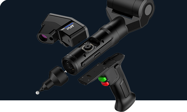
Complex surfaces create a measurement challenge because their geometry cannot always be represented efficiently through a limited number of contact points. Curves, freeform contours, recessed features, and changing surface directions require dense spatial data to describe accurately. A CMM laser scanner addresses this challenge by collecting large numbers of points across a surface and converting them into digital measurement data for inspection and comparison.
Why Complex Surfaces Need More Than Point-by-Point Measurement
Traditional tactile measurement can provide highly accurate information at selected locations, but complex geometry may require a substantial number of individual points to represent its actual form. This can make inspection slower when manufacturers need to evaluate broad or continuously changing surfaces.
Laser scanning takes a different approach. A laser sensor projects a beam or line onto the workpiece while the system determines the position of the illuminated surface. As the scanner moves across the component, it generates a point cloud representing the surface geometry. CMM laser scanners can therefore collect much more surface information than isolated probing points.
This approach is particularly useful for automotive components, molded parts, castings, aerospace structures, tooling, and other manufactured components where dimensional conformity depends on the shape of an entire surface rather than only several reference points.
How a CMM Laser Scanner Captures Surface Geometry
A CMM laser scanner typically works together with a coordinate measuring machine or articulated measuring system. As the scanner moves, the system continuously determines the sensor’s position and orientation. The laser data can then be transformed into a common coordinate system to build a three-dimensional representation of the component.
The resulting point cloud contains spatial information across the scanned area. Metrology software can use this data for applications such as CAD comparison, dimensional inspection, deviation analysis, and surface evaluation. Full-surface scanning is especially valuable when engineers need to understand where a manufactured part differs from its nominal geometry.
The Role of Measuring arm Flexibility
The configuration of the measuring arm can strongly influence how effectively a scanner reaches complicated geometry. Articulated arms use multiple rotational axes to position a probe or scanner around a workpiece. This gives operators considerable flexibility when approaching surfaces from different directions.
For parts with curved sections, deep features, or irregular contours, the operator can change the scanner’s orientation while maintaining measurement coverage. Portable articulated systems can also be brought directly to a component rather than requiring every part to be transported to a fixed inspection machine. ZEISS notes that articulated portable CMMs can support both tactile probes and laser scanners, making them adaptable to different inspection requirements.
The practical advantage of a measuring arm is therefore not simply portability. Its articulated movement can help the scanner follow the geometry of a component and access areas that would be inconvenient to inspect using a rigid setup.
Multiple Scanning Modes Improve Coverage
Complex surfaces rarely have identical measurement conditions from one feature to another. A broad exterior surface may be straightforward to scan, while a narrow recess, curved transition, or complicated edge may require a different scanning approach.
Multiple scanning modes can help operators adapt the measurement process to these changing conditions. Rather than treating every surface in exactly the same way, the operator can select an appropriate mode according to the geometry and inspection task.
This flexibility is particularly relevant for portable inspection teams. When a single component contains several types of surfaces, changing scanning approaches without completely rebuilding the measurement setup can make the workflow more practical and efficient.
Calibration Matters for Reliable Results
Collecting a large point cloud does not automatically guarantee useful measurement results. The scanner must be properly calibrated so that the relationship between the optical system and measurement coordinates remains reliable.
A visual calibration interface can simplify this process by guiding the operator through calibration steps. For B2B users, easier calibration is valuable because inspection efficiency depends not only on scanning speed but also on setup time, operator consistency, and repeatability.
The PMT GAMMA 7/8-AXIS+GH/GS Series incorporates a visual calibration interface intended to make calibration easier and improve measurement efficiency. Its optical design is also optimized for more stable scanning accuracy, providing a practical combination of scanning flexibility and measurement stability.
Handling Operator and Surface Challenges
Scanning performance also depends on the interaction between the optical sensor, the operator, and the workpiece. The scanner needs to capture sufficient surface information while the operator maintains an appropriate scanning path and sensor position.
Operator comfort can therefore influence practical inspection efficiency. The PMT GAMMA SCANNER includes an eye protection mode that allows users to adjust laser brightness to help ease eye fatigue. While this feature does not replace proper laser safety practices, it addresses an important ergonomic consideration during scanning work.
The scanner’s multiple scanning modes also help users adapt to complex scenes, supporting measurement flexibility when component geometry changes across the inspection area.
Turning Scanned Data Into Manufacturing Decisions
The real value of laser scanning appears after data collection. A point cloud can be compared with nominal CAD geometry to identify dimensional deviations, deformation, missing features, or areas outside specified tolerances. Full-field data can also provide a broader picture of part quality than a small selection of manually measured points.
For manufacturers, this can support inspection, first-article verification, reverse engineering, process troubleshooting, and quality control. The appropriate measurement strategy still depends on required accuracy, part material, geometry, environment, and software workflow. Portable CMM selection should likewise consider complexity, accuracy, part size, measurement speed, and application requirements.
Choosing the Right Approach for Complex Parts
A CMM laser scanner is not simply a faster substitute for a tactile probe. Its strength lies in capturing extensive surface information efficiently. When a component contains freeform geometry, continuous curves, or many changing surface features, dense optical data can provide a more complete basis for analysis.
A suitable measuring arm can further improve accessibility by allowing the scanner to approach the workpiece from multiple orientations. Combined with appropriate calibration and scanning modes, this creates a flexible inspection workflow for manufacturers handling diverse component geometries.
A Practical Solution for Complex Surface Inspection
For companies evaluating portable 3D inspection equipment, the PMT GAMMA 7/8-AXIS+GH/GS Series combines an optimized optical design, a visual calibration interface, multiple scanning modes, and adjustable laser brightness through its eye protection mode. These features position the system as a practical option for B2B users seeking flexible surface measurement with a portable measuring arm configuration. Ultimately, the effectiveness of any CMM laser scanner depends on matching its scanning capabilities, measurement strategy, and workflow to the geometry and quality requirements of the parts being inspected.
